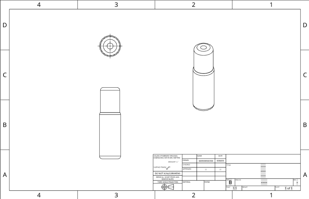
In this section, the technical drawings of the manual hand drill and its main components are presented. Technical drawings are important because they show the product in a clear, detailed, and standardized way. Unlike the 3D model, these drawings focus on the shape, projection views, and assembly relationships of the parts.
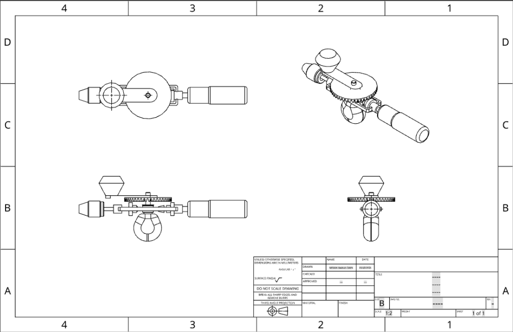
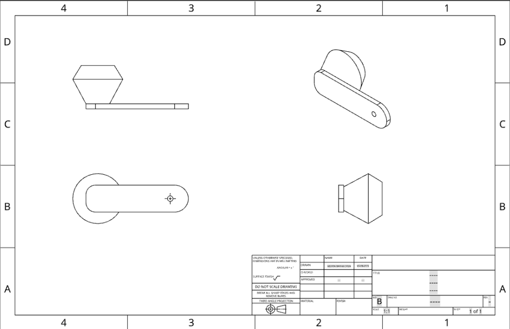
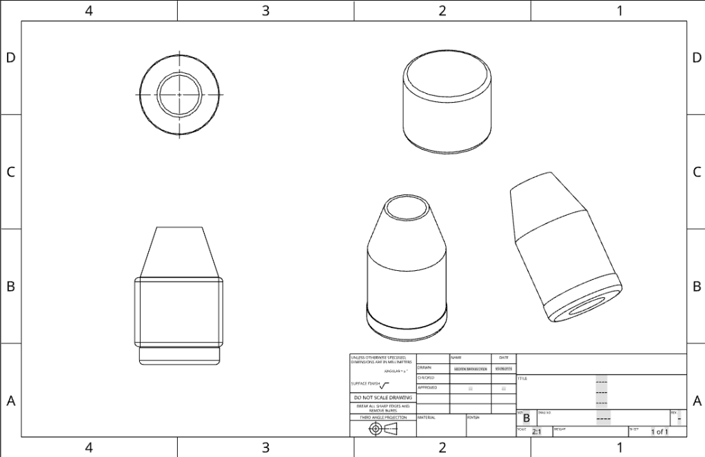
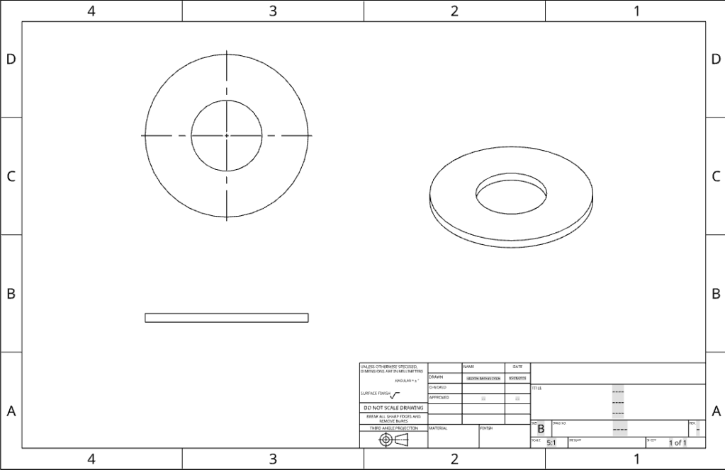
The drawings include different views such as front view, top view, side view, and isometric view. These views help explain the geometry of each part more accurately. Some drawings show individual components such as the handle, chuck, gear, washer, shaft, and body frame. Other drawings show the complete assembly of the manual hand drill. By using multiple views, it becomes easier to understand the size, position, and connection of each component.
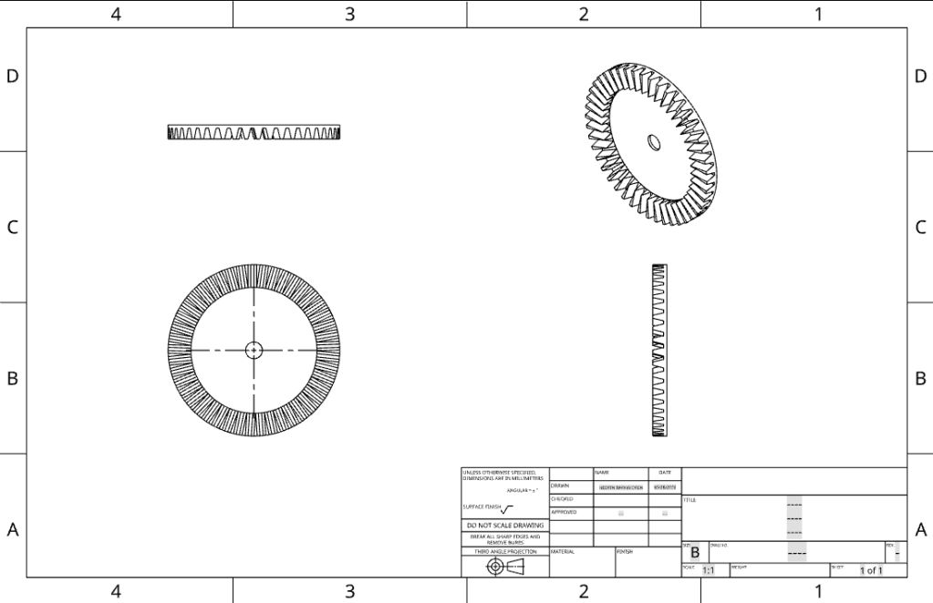
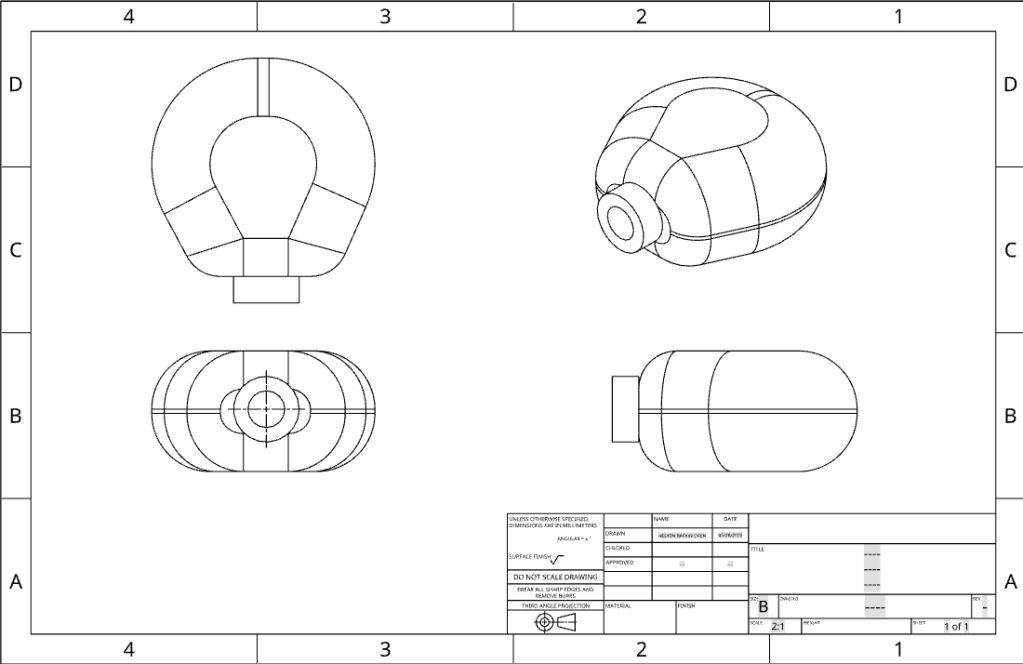
The gear drawing is one of the most important parts because the gear system transfers the rotational motion from the handle to the spindle. The teeth of the gear are shown clearly to represent the motion transmission mechanism. The chuck drawing shows the front part of the drill, which holds the drill bit during operation. The handle and body frame drawings show how the user applies force and how the structure supports the mechanism.
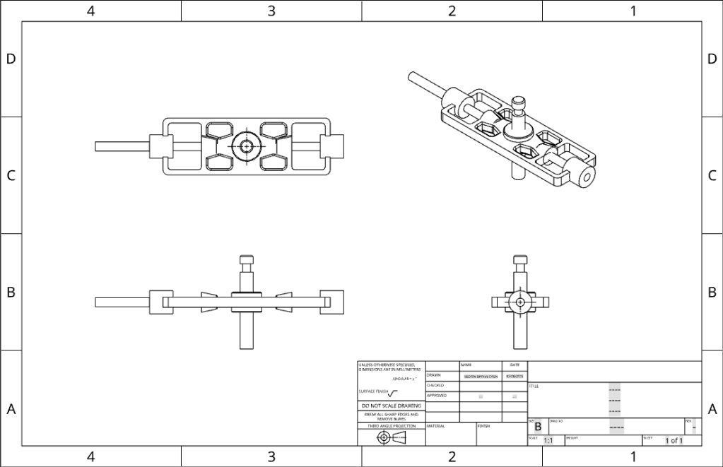
The assembly technical drawing shows how all parts are placed together in the final product. It demonstrates the alignment between the handle, gear, spindle, and chuck. This alignment is important because the drill can only work properly if the rotational motion is transferred smoothly through these parts.
Overall, the technical drawings support the design process by making the product easier to analyze and explain. They show the manual hand drill not only as a 3D model but also as an engineering design with separate components, projection views, and assembly details. Therefore, this section is an important part of documenting the product design.