In this part of the project, the manual hand drill was assembled by combining the separately modeled components in CAD software. The main purpose of the assembly stage was to show how each part fits together and how the complete mechanism works as a single product. Instead of focusing only on individual parts, this stage explains the relationship between the components.
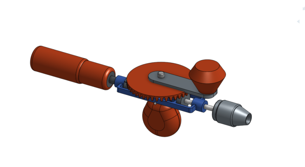
The assembly includes the main frame, handle, gear system, spindle, chuck, rotating arm, side supports, and connection elements. The frame acts as the main support structure and keeps the other parts in the correct position. The large gear is connected to the rotating handle, and it transfers the hand motion to the spindle. The spindle then carries this rotational motion to the chuck, which holds the drill bit securely during use.
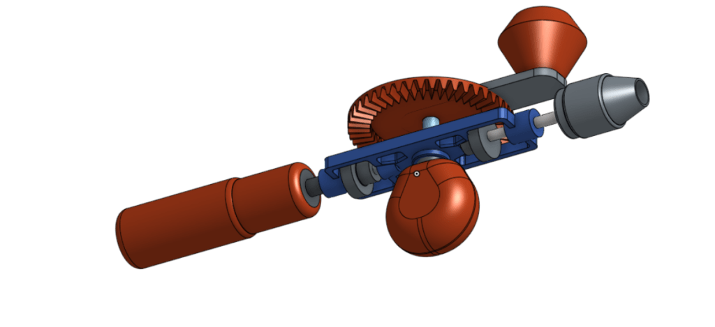
Different colors were used in the assembly to make the components easier to identify. The blue part represents the main frame, the orange parts show the gear and handles, and the grey parts represent metal components such as the spindle, chuck, and fasteners. This color separation makes the assembly clearer and helps explain the function of each part.
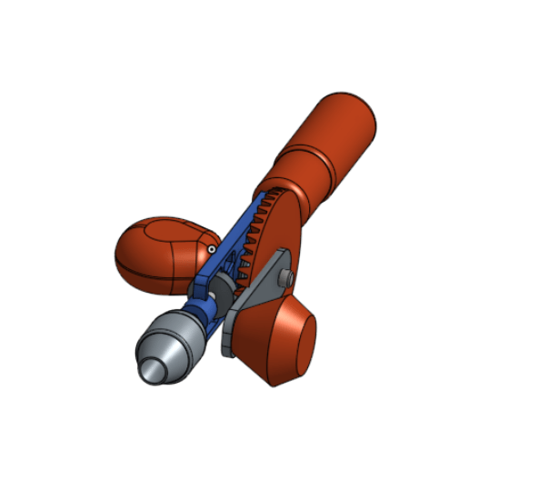
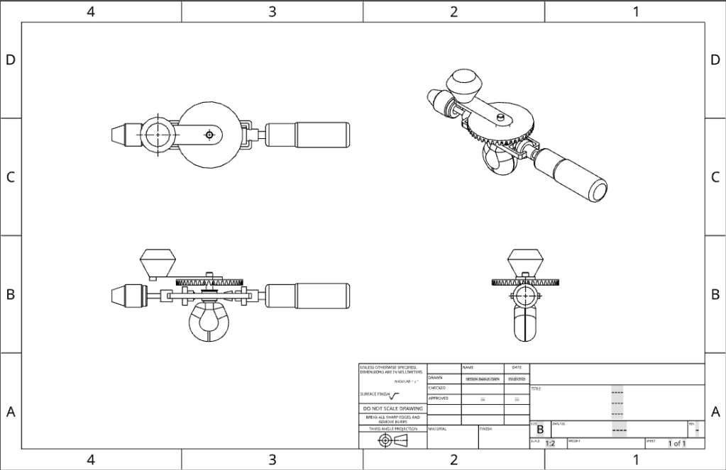
The assembly views were taken from different angles to show the product more clearly. These views help demonstrate the position of the gear system, the connection between the handle and the shaft, and the alignment of the chuck with the spindle. They also show how the manual force applied by the user is converted into rotational drilling motion.
Overall, the assembly process helped us understand the working principle of the manual hand drill more clearly. It shows that the drill depends on proper alignment between the handle, gear, spindle, and chuck. Therefore, the assembly model is an important part of presenting both the mechanical structure and the function of the product.